everlasting turn signal switch wiring
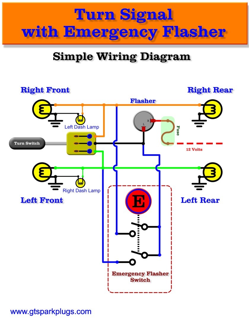
Depending on the position of the turn-signal stalk, the power either stops in the switch or gets sent to the left or right turn-signal lights (including the indicator lights on the dashboard). Power flows through the filament of the lights and then is grounded.
7 Wire Turn Signal Switch Wiring Diagram Database
This article will provide you with a turn signal wiring diagram for a 7-wire system. This diagram will show you how to connect the turn signal switch, turn signal bulbs, and flasher to your vehicle's electrical system. ## Turn Signal Switch The turn signal switch is a lever-operated switch that is located on the steering column of your vehicle.

PM 500 7Wire Turn Signal Switch
SKU: HL101 Universal Turn Signal Switch 7 Wire W/ Indicator Light & Emergency Flasher Button $41.95 Qty Description Description Details - Mounted Length: 7.75" Number of Positions: Three Material Type: Plastic Finish: Chrome Notes: Includes 4-way flasher function. Info - Chrome plated finish.
Yamaha Golf Cart Turn Signal Wiring Diagram Wiring Diagram Schemas
OEM-Style Turn Signal Switch For PACCAR®. Freightliner® OEM Replacement Switch. Universal Replacement Harness. OEM-Style Marker Flash & Wiper Turn Signal Switch For International®. keyboard_arrow_left. keyboard_arrow_right. Grote Industries - Part: #48072 - Universal 7-Wire 4-Wire Turn Signal Switch Kit, Turn Signal Switch Kit. 4- or 7-wire.
Aftermarket Turn Signal Switch Wiring Diagram Collection
In this video we wire a turn signal, brake light, parking light and hazard light switch (4-way flasher) circuit. I use the American Autowire 500148 turn signal switch, along with two.
Wiring Diagram Turn Signal Switch Collection
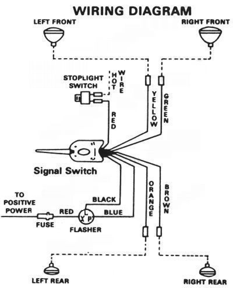
For 7 wire systems, this is where the turn signal wiring diagram comes in handy. A turn signal wiring diagram for 7 wire systems provides detailed information about the wiring of the signal. It includes which wires are used for what purpose and the colors of each wire.
Basic Brake Light Switch Wiring Diagram
A 7 wire turn signal switch diagram is a visual representation of the wiring connections that make up this important switch. Understanding how the wires are connected is crucial for diagnosing and repairing any issues that may arise with the turn signal system.
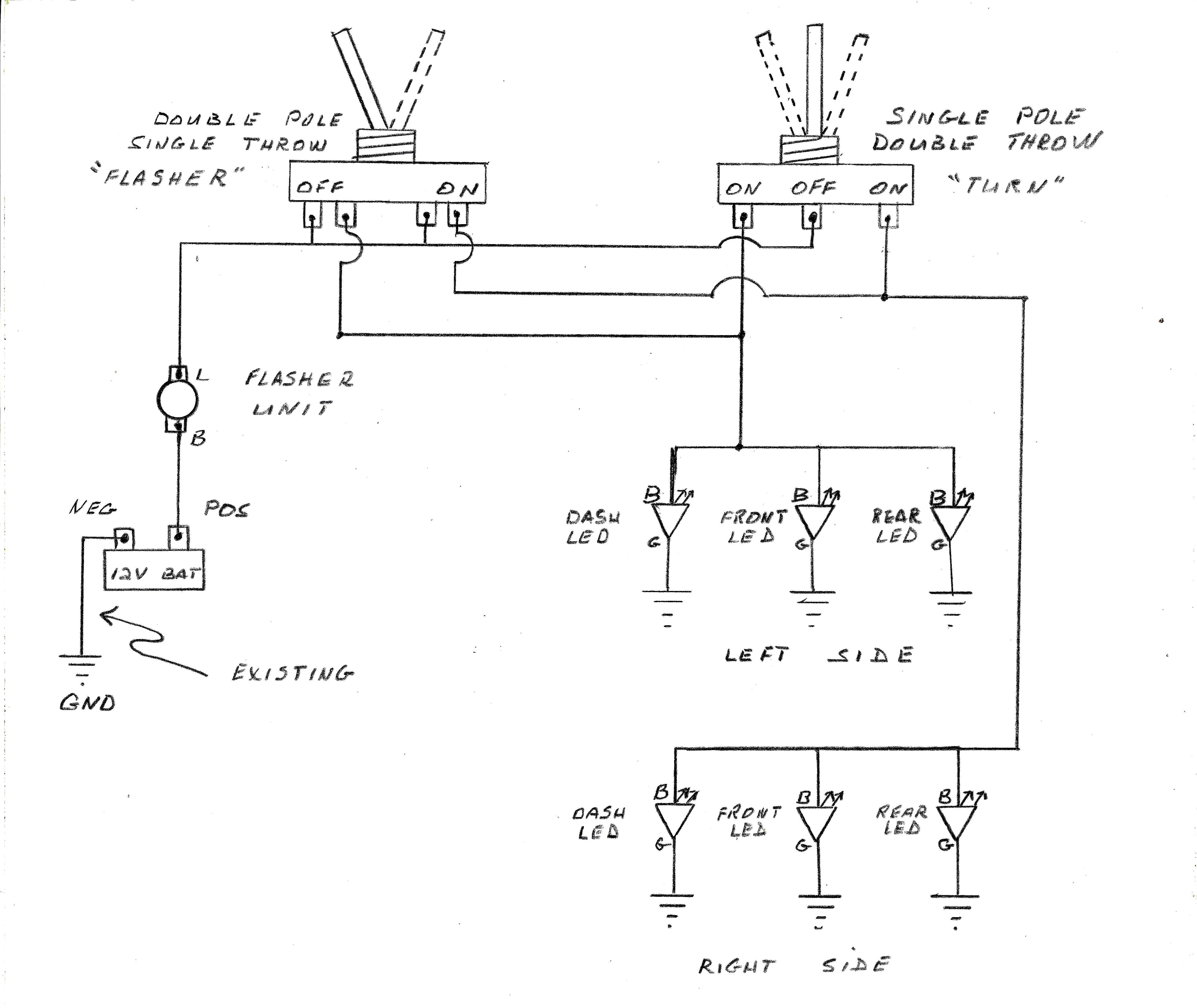
Flasher Unit Circuit Diagram
Technical Signal Stat 7 wire Discussion in ' Traditional Customs ' started by Chop50, Apr 4, 2021 . Chop50 ALLIANCE MEMBER from North Shore, MA Hi All, Have installed a 7 wire 900 series Signal Stat in my car. All directional and flashers are working but for some reason I now have no brake lights. They were working before the Signal Stat install.
Universal Turn Signal Switch Wiring Diagram Cadician's Blog
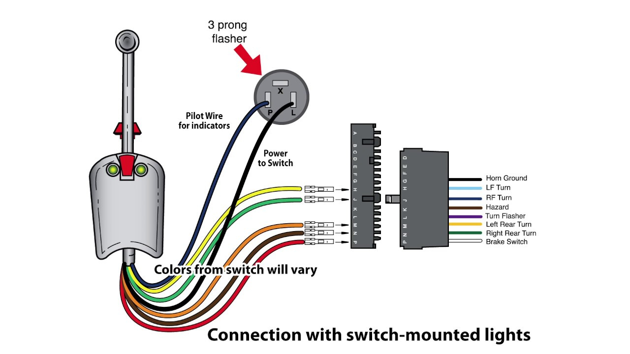
turn signal switch with integral pilot lamps . typical grote tss wiring diagram . typical tss terminal location diagram . grote tss maximum loads. left front turn-green typical wiring . continuity diagram 3456 7 8 9 functions headl dimmer 2 stop rn turn turn turn ight rear

Wiring Diagram For 7 Wire Turn Signal Switches Replacement Youtube
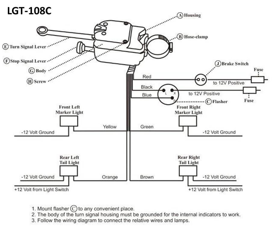
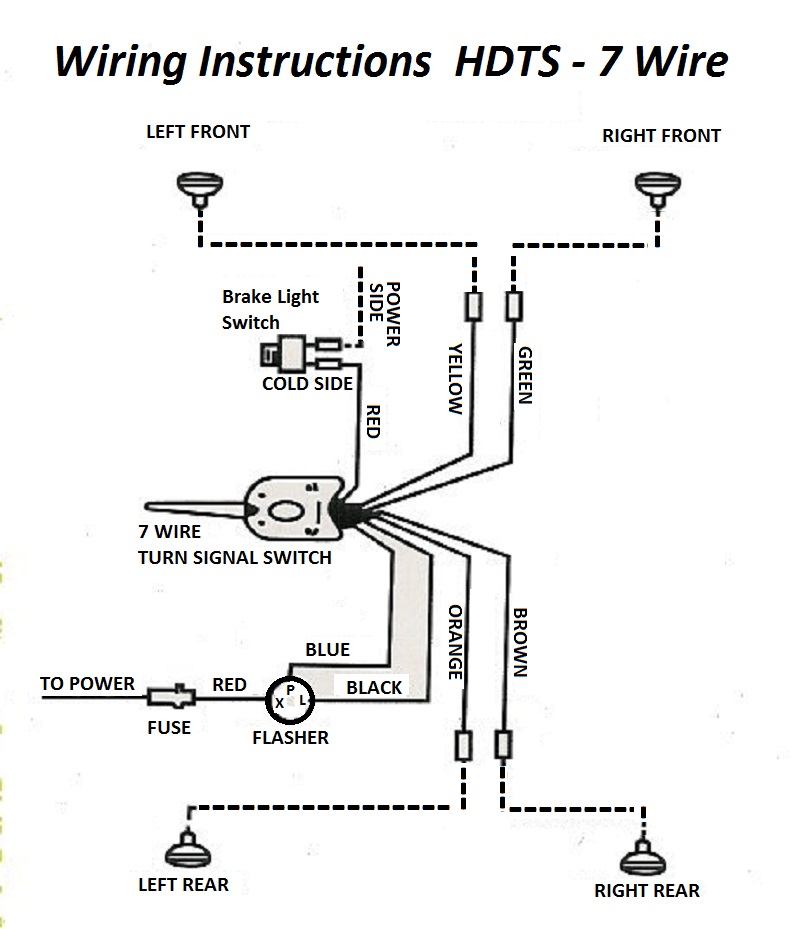
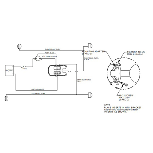
Green to the right front signal Yellow to the left front Brown to the right rear Orange to left rear Red to the stop switch Black & Blue to the Flasher " The referenced vendor is http://www.jeepdoc.com/ and the turn signal in question appears to be the Everlasting and is part number 947348 (17232.01)

Signal Circuit Diagram
This allows the turn signal to be active in the rear while also allowing the brake light to be active on the otherside. #4 Front left marker - This will only be active when the signal is switched to the 'left' side and when the four way flasher is active. #5 Rear left marker/brake - This will be active with the brake light on and the turn.

7 Wire Turn Signal Switch Wiring Diagram Database
To Operate Flare: With switch handle in neutral position, pull flare tab out. All signal Move switch handle left or right. Tab flare will release automatically. Return switch handle to neutral position. * Exclusive of pilot lights

Load Wiring Universal Turn Signal Wiring Diagram
Turn signal switch wiring diagrams can be found online and are relatively simple to understand. They can also be consulted while troubleshooting existing switch wiring. When installing a new switch, the wiring diagram should be checked against the actual wiring of the vehicle. This will ensure that the switch is wired correctly and will work as.

Frank Wiring Wiring Diagram For 7 Wire Turn Signal Switch Diagram
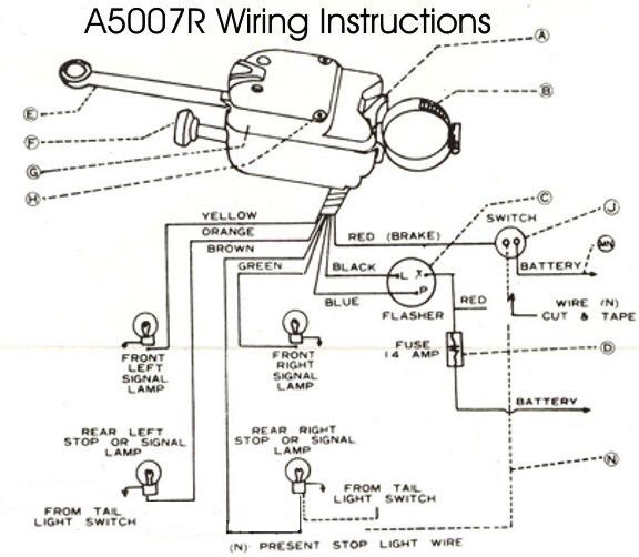
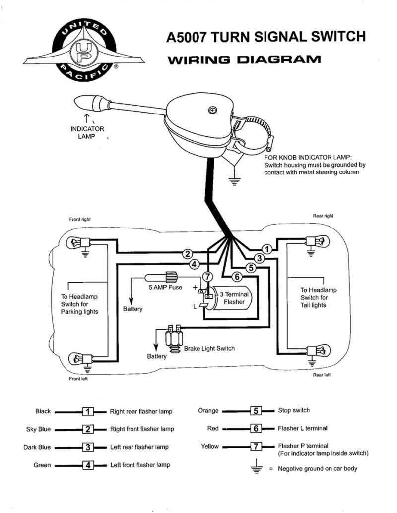
Do you need a universal turn signal switch for your vehicle? Check out this United Pacific A5007 model that clamps on the steering column and has a chrome finish. It comes with 7 wires, a fuse, a green indicator light and a wiring diagram. Easy to install and compatible with 12 volt systems.
Bestof You Top Simple Turn Signal Wiring Diagram Of The Decade Don'T
Amazon.com: United Pacific Chrome 12V Universal Turn Signal Switch Replacement for Early Cars & Trucks, 7-Wire System, Adjustable Steering Column Clamp - 1 Unit : Automotive Automotive › Replacement Parts › Body & Trim › Trim › Interior › Interior Switches › Turn Signal $2539 FREE delivery Thursday, December 7. Order within 10 hrs 24 mins. Details
Load Wiring 7 Wire Turn Signal Switch Wiring Diagram
A 7 wire universal turn signal switch is a device that will allow you to control the signals your vehicle sends to other drivers. It is usually located near the steering wheel and is connected to the turn signal lights.