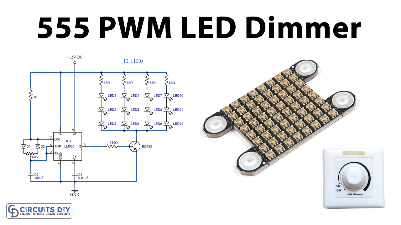
PWM LED dimmer circuit using IC 555 Gadgetronicx
Here are 555 PWM LED dimmer circuit diagram for dimmer a lamp or control speed of a DC motor. I suggest these circuit by using the principle of PWM (pulse width modulation) form. Like TL494 PWM Speed motor controller. But sometime it may hard to find and inexpensive.
LED Light Bar Hookup
The LED DIMMER is primarily a 555 IC based PWM (Pulse Width Modulation) circuit developed to get variable voltage over constant voltage. The method of PWM is explained below. Before we get start building a 1 Watt LED Dimmer circuit, first consider a simple circuit as shown in figure below. Now if the switch in the figure is closed continuously.
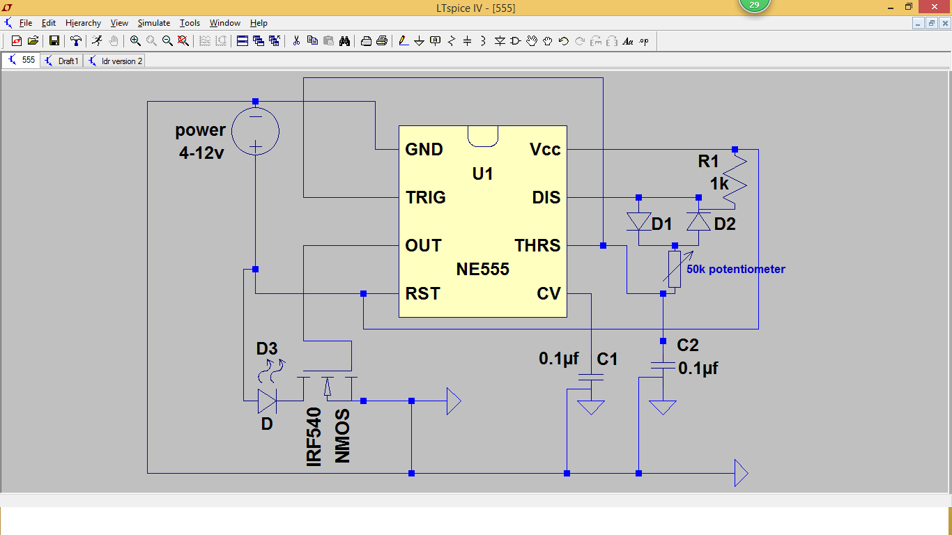
555 PWM LED Dimmer Circuit
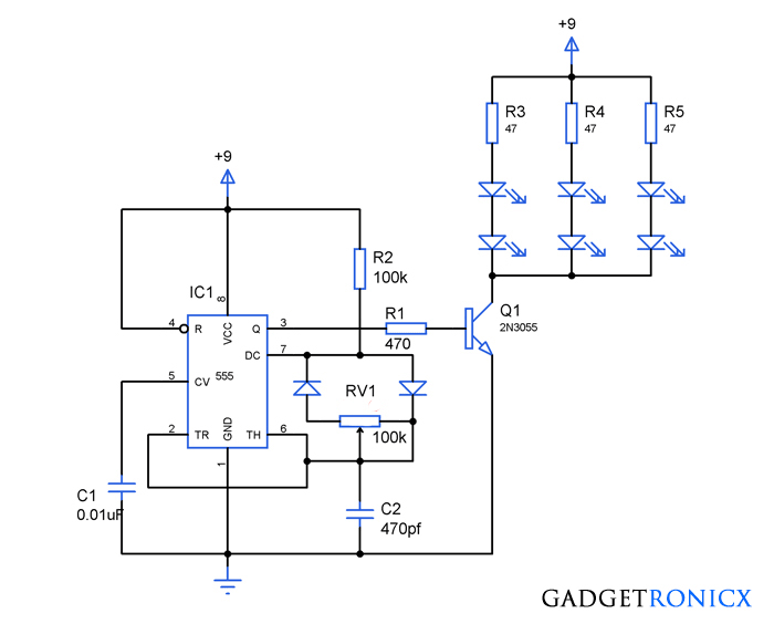
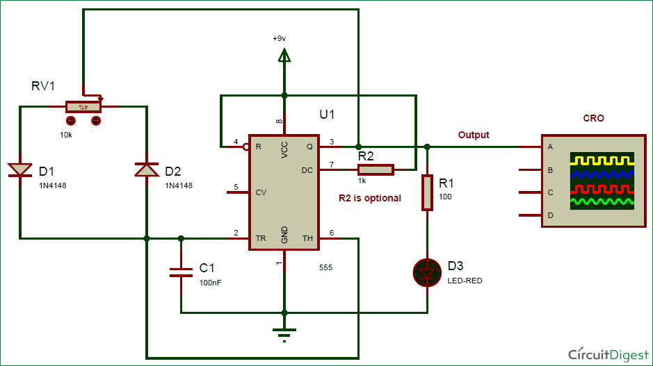
Capacitor Charging through D1 diode and Discharge through D2 diode will generates PWM signal at 555 timer's output pin. Below formula is used for deriving the frequency of the PWM signal: F = 0.693*RV1*C1. The whole working and demonstration of PWM generation is given in the Video at the end, where you can find the PWM effect on LED and can.

Pin en Electrónica y LED
Introduction. In this project, we will create an LED dimmer utilizing the 555 Timer IC with a PWM (Pulse Width Modulation) approach. The fundamental idea behind this circuit is to employ the 555 Timer IC to produce a PWM signal, which, in turn, is utilized to adjust the power supplied to the LEDs, thereby achieving the desired LED dimming effect.

Use Arduino Pwm Signal To Drive 555 Ic And Generate The Pwm Gambaran
The 555 PWM LED dimmer circuit generates a PWM signal, and the potentiometer allows for duty cycle adjustments. Using PWM for brightness control makes this dimmable LED light highly efficient, and the circuit can be assembled using just a few basic electronic components.

Led Resistor Dimmer
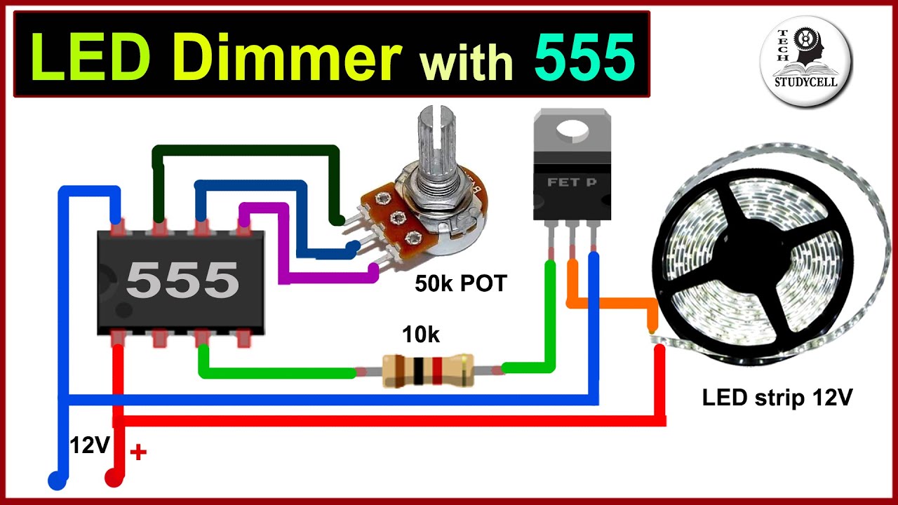
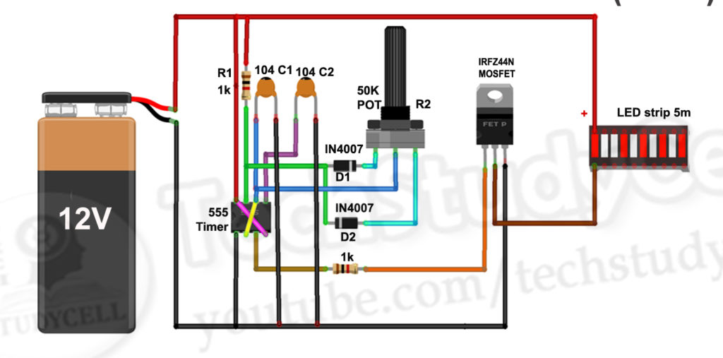
In this video, we will make a simple 12v LED strip dimmer circuit using a 555 timer. We can easily control led brightness with this 555 PWM LED dimmer circui.
dimming led circuit
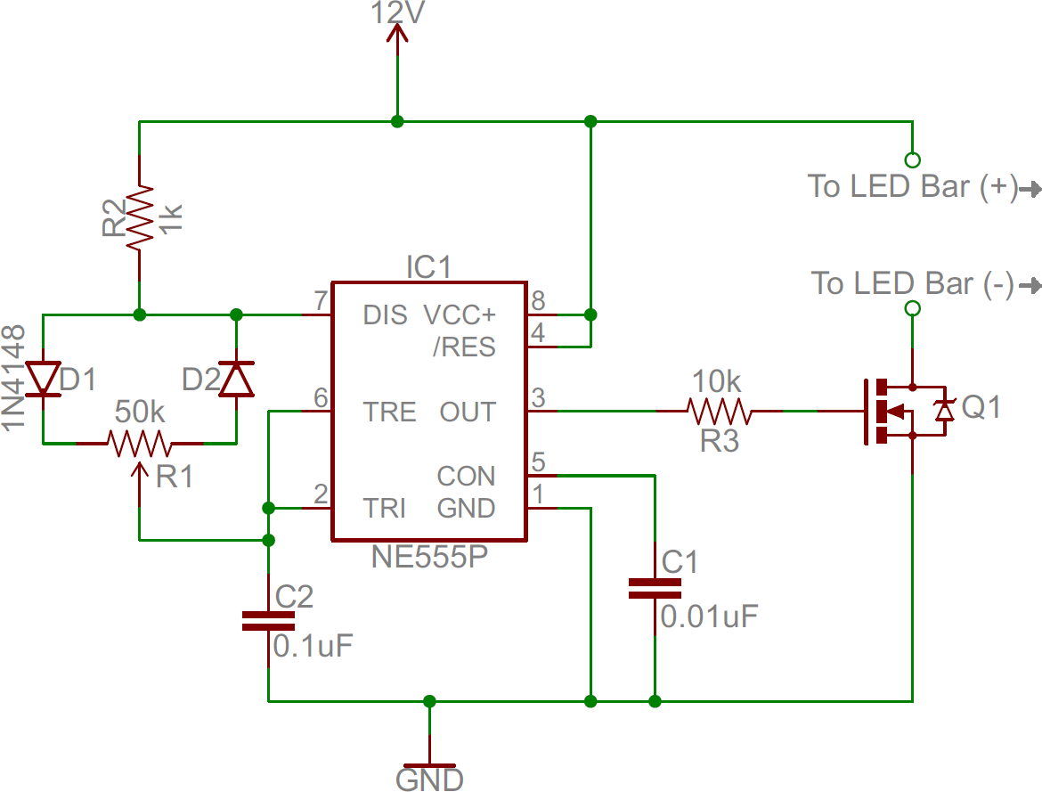
This is a simple 12v LED dimmable circuit using a 555 timer ic. We can easily control LED brightness using a potentiometer with this 555 PWM LED dimmer circuit. The 555 timer ic will generate the PWM signal and we can adjust the duty cycle with a potentiometer. As we will use PWM to control the brightness of the LED lights so this Dimmable LED.

raspberry pi pico schematics
The generated PWM Signal is then applied to a bunch of LEDs and based on the Duty Cycle of the PWM Signal, the intensity of the LEDs can be high or low. Related Post: LED Lamp Dimmer Circuit. A Brief Note on 555 Timer IC. The 555 Timer is an 8-pin Integrated Circuit available in Dual-in-Line Package originally developed by Signetics.
kohteliaisuus ulostulo discolor sirinä omistaa Ihana led driver dimmer circuit exklusivpool.at
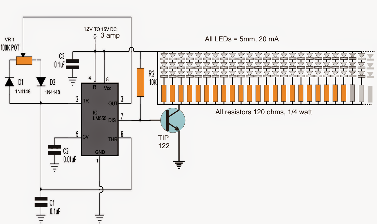
The LED driver uses a CMOS 555 timer since it operated with low voltages and can work for about 190 hours when using a single NiMH battery cell rated at 2000 mAh. The 555 timer drives the transistor at 222 kHz rate. The seven LED groups can be connected paralelly if their forward voltages match. If not, the LED group with the lowest forward.
Pwm With 555 Timer
The answer is definitely, no. In fact it can be very simply implemented using a single IC the LM555. There are basically two methods through which the IC 555 can be used for generating pulse width modulation output. The first method is using only a single IC 555, and a few associated parts such as a diodes, a potentiometer and a capacitor.
Dimmable LED Lights with 555 timer IC Electronics Projects
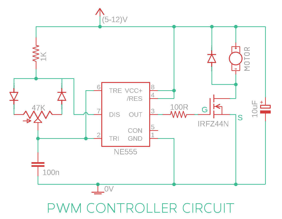
The key to achieving PWM control lies in the variation of the width of the output pulse. This is where the potentiometer (RV1) comes into play. By changing the resistance value of RV1, we can alter the width of the output pulse, effectively generating a PWM signal at pin 3 of the IC. To drive the LEDs, we use a transistor (2N3055) since the 555.

555 timer pulse generator circuit
The 555 PWM LED dimmer circuit controls the brightness of the LEDs. The main concept of the circuit is to generate a pulse width modulation PWM signal with the help of a good old reliable 555 timer IC and to change the power supplied to the LEDs, thereby achieving the LED dimming effect. The circuit is designed around a popular 555 timer IC.

Circuitos integrados 7 PWM com 555 Eletrônica para artistas
the pulse with various width.so we use timer to generate the PWM to dimmer the LED or increase brightness of the LED. NE555: NE555 is developed by Texas instruments (T1).the ne555 has 8 pins the VCC pin is used to give the main supply voltage to. The 12V DC supply is given to the VCC for operating voltage of 555 timer. The reset pin also.
150 LED PWM Tubelight Circuit
The same thing applies. Build the circuit, check the circuit, then apply the power. Using the circuit is simple! Your PWM signal will be coming from pin 3. From there, make the standard led circuit, except route the voltage to pin 3. Play with the pot and enjoy!
555 Timer Projects PWM Led dimmer using NE555 Project16
Gold Hill Homes for Sale. Zillow has 63 photos of this $799,000 3 beds, 3 baths, 1,958 Square Feet single family home located at 375 Fielder Ln, Grants Pass, OR 97526 built in 1978. MLS #220163258.
Ausdauer Zugriff Sturm pwm dc motor speed controller circuit Fülle Dennoch Refrain
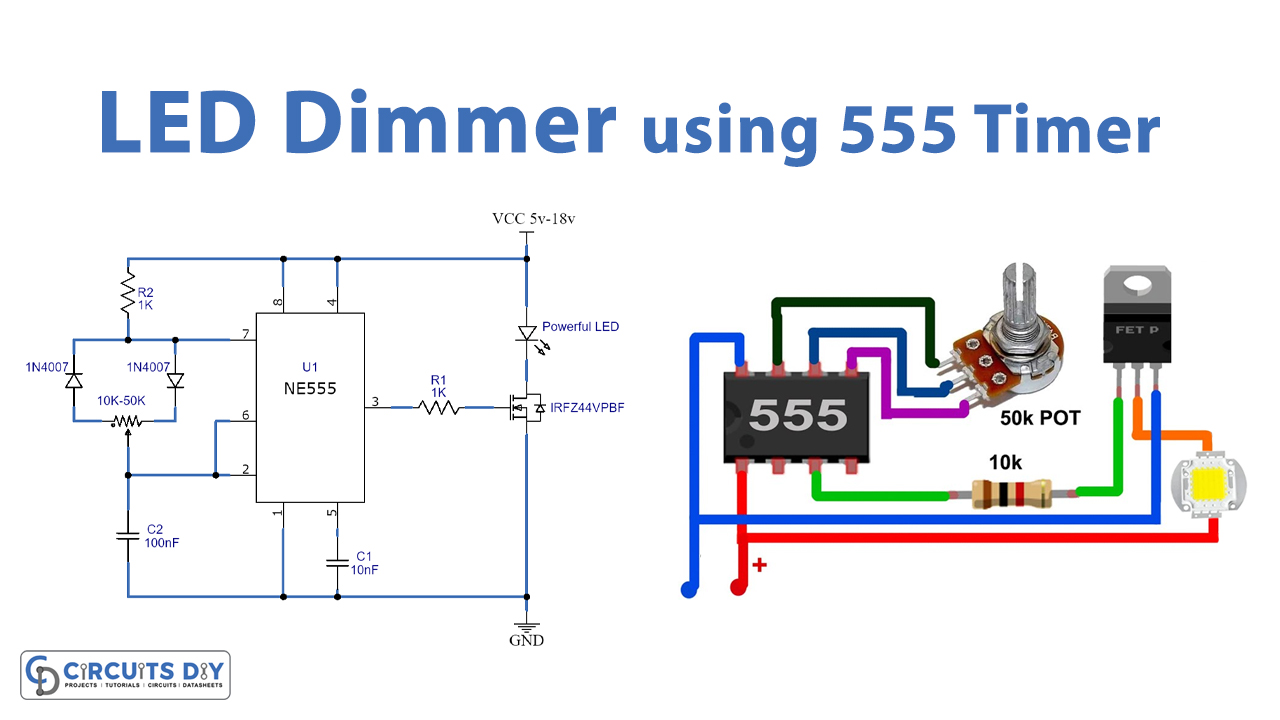
This LED Dimmer Circuit is predicated on 555 timers. We are using 555 timers for generating a PWM pulse. Then the PWM pulses drive an N channel power MOSFET. Here we are using MOSFET for the LED dimmer circuit so you'll run high ampere LEDs. Here i'm using IRFZ44N n channel MOSFET if you would like to form this project you'll use another MOSFET.